Home

Cina Manoscritto crociera compressor pv diagram venti forte Come

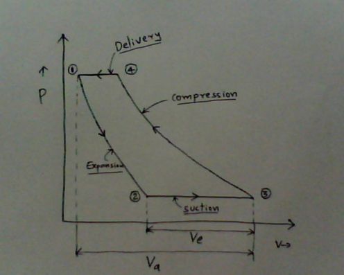
Explain working of single stage reciprocating compressor with P-V diagram.

Module 5 - PV diagram of Multistage reciprocating air compressor with  intercooler & workdone - YouTube
Module 5 - PV diagram of Multistage reciprocating air compressor with intercooler & workdone - YouTube

Single Stage Air Compressor Basic Theory With PV Diagram Explanation

2 Reciprocating Air Compressors (Working and p-v diagram) - YouTube

6: p-v diagram for reciprocating and screw compressor. | Download  Scientific Diagram
6: p-v diagram for reciprocating and screw compressor. | Download Scientific Diagram

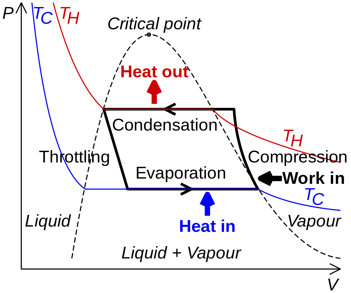
Vapor-Compression Refrigeration | Refrigerator, Vapor, Compression

The compressor indicator diagram - YouTube

The actual PV diagram of reciprocating compressor | Download Scientific  Diagram
The actual PV diagram of reciprocating compressor | Download Scientific Diagram

Part2] Reciprocating compression of air – Thermodynamics on PV and TS  diagram
Part2] Reciprocating compression of air – Thermodynamics on PV and TS diagram

Two Stage Compressor | How does a 2 Stage Air Compressor work?

P-V Indicator Diagram with solved Examples

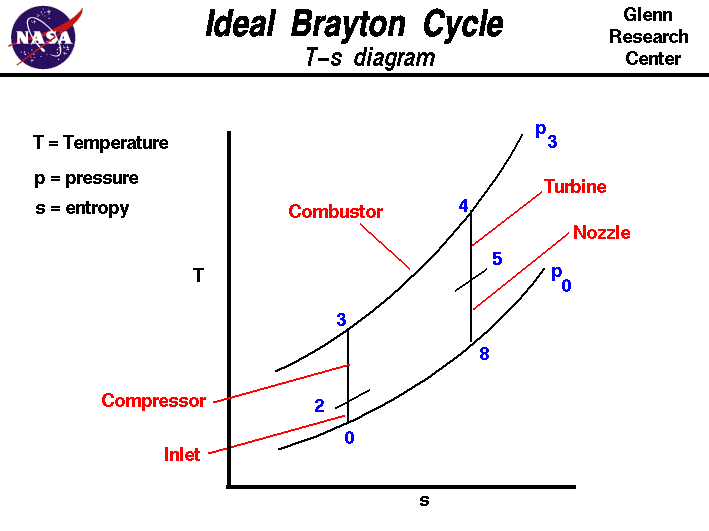
Turbine Engine Thermodynamic Cycle - Brayton Cycle

P-V diagram showing compression (⇣c) and expansion (⇣e) trajectories.... |  Download Scientific Diagram
P-V diagram showing compression (⇣c) and expansion (⇣e) trajectories.... | Download Scientific Diagram
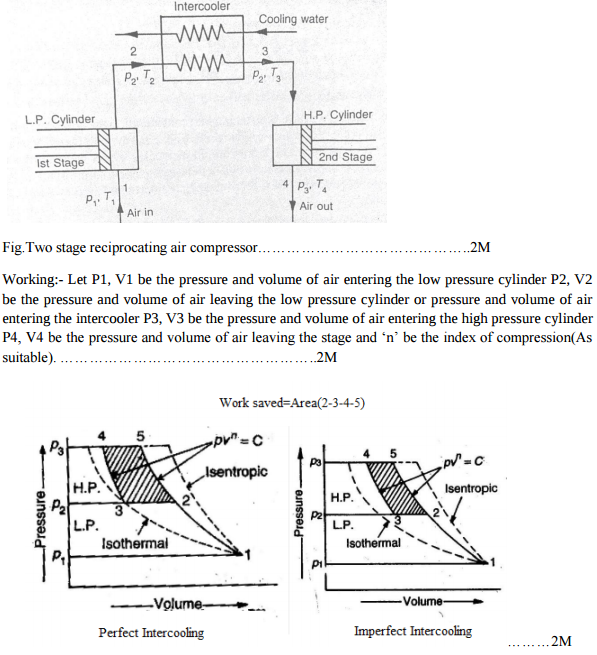
Explain the working of two stage reciprocating compressor....... |  Mechanical Engg Simple Notes ,Solved problems and Videos
Explain the working of two stage reciprocating compressor....... | Mechanical Engg Simple Notes ,Solved problems and Videos

Vapor-compression refrigeration - Wikipedia

Experimental Pressure-Volume diagrams of scroll compressors

Air Compressor Operation: Description of Two Stage and Theory

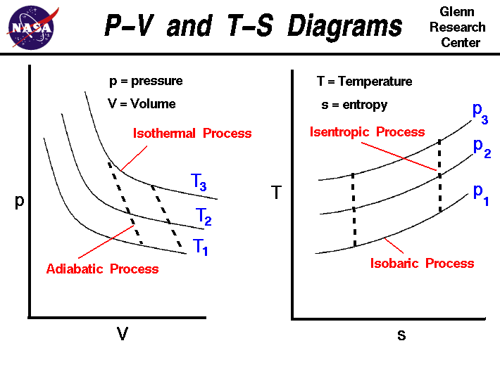
P-V and T-S Diagrams

UC or OC of a PD compressor on P-V diagram, Huang [5] | Download Scientific  Diagram
UC or OC of a PD compressor on P-V diagram, Huang [5] | Download Scientific Diagram

Performance Analysis of Rolling Piston Type Rotary Compressor for Household  Refrigerators | Semantic Scholar
Performance Analysis of Rolling Piston Type Rotary Compressor for Household Refrigerators | Semantic Scholar

Thermodynamics: Lesson 32. AIR COMPRESSOR'S WORK, NUMERICAL PROBLEMS

Part2] Reciprocating compression of air – Thermodynamics on PV and TS  diagram
Part2] Reciprocating compression of air – Thermodynamics on PV and TS diagram

Compressors – Working and Characteristics

Solved] The pressure-volume diagram of an ideal reciprocating air co

Detecting cracks in reciprocating compressor valves using pattern  recognition in the pV diagram | Pattern Analysis and Applications
Detecting cracks in reciprocating compressor valves using pattern recognition in the pV diagram | Pattern Analysis and Applications
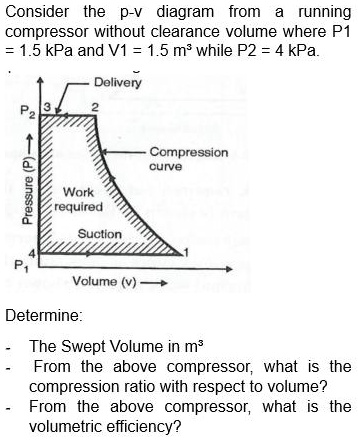
Fig. 32.1 PV Diagram of single stage reciprocating air-compressor

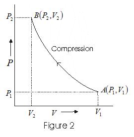
SOLVED: Title: Please Provide Answer and Solution Consider the p-v diagram  from a running compressor without clearance volume where P1 = 1.5 kPa and  V1 = 1.5 m while P2 = 4
SOLVED: Title: Please Provide Answer and Solution Consider the p-v diagram from a running compressor without clearance volume where P1 = 1.5 kPa and V1 = 1.5 m while P2 = 4